 Online Contact
 Send Message
How to Adjust Flat Die Pellet Mill Reverse Rotation Correctly
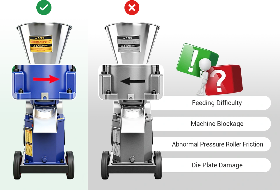
Motor reversal may occur after motor installation or service. Wrong rotation affects feeding and pellet quality and can damage the die. Always verify the rotation direction. The steps below apply to both single phase and three phase motors.
How to confirm die rotation direction
Before making any adjustment, confirm whether the machine is actually reversing.
Check methods
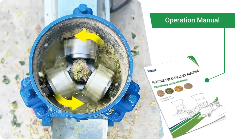
1. Observe the die from the feed inlet
Run the machine shortly and look down at the die. Most flat die mills rotate counterclockwise, but follow the direction shown on the nameplate or manual.
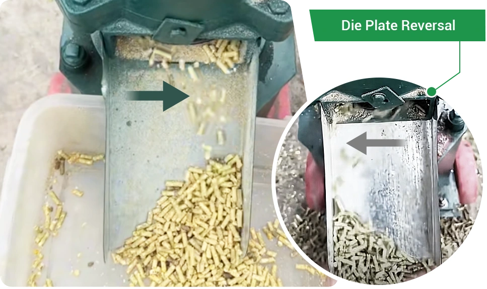
2. If the die cannot be seen, check the discharge pattern
Add a small amount of material. With correct rotation, pellets move toward the right side of the outlet. If they shift left, the motor is likely reversed.
Effects of die reversal
The die rotation determines the material flow and compression path. When the direction is reversed, the pelletizing process is disrupted and may lead to:
- Abnormal friction and heat between the rollers and die, causing faster wear
- Poor pellet formation
- Material being pushed in the wrong direction, leading to no feeding or roller slip
- Lower pelletizing efficiency
- Abnormal load current or motor overheating
The die rotation depends on the motor direction. Pellet mills use either single phase or three phase motors, and the adjustment method differs for each. The sections below explain both.
Safety notes and tips
- Cut power fully before any wiring work.
- After rewiring or motor replacement, run a short test to confirm proper rotation and roller condition.
- Stop the machine immediately if reversal occurs to prevent wear or blockage.
Single phase motor rotation and adjustment
Small pellet mills, typically below 200 kg per hour, use single phase motors.
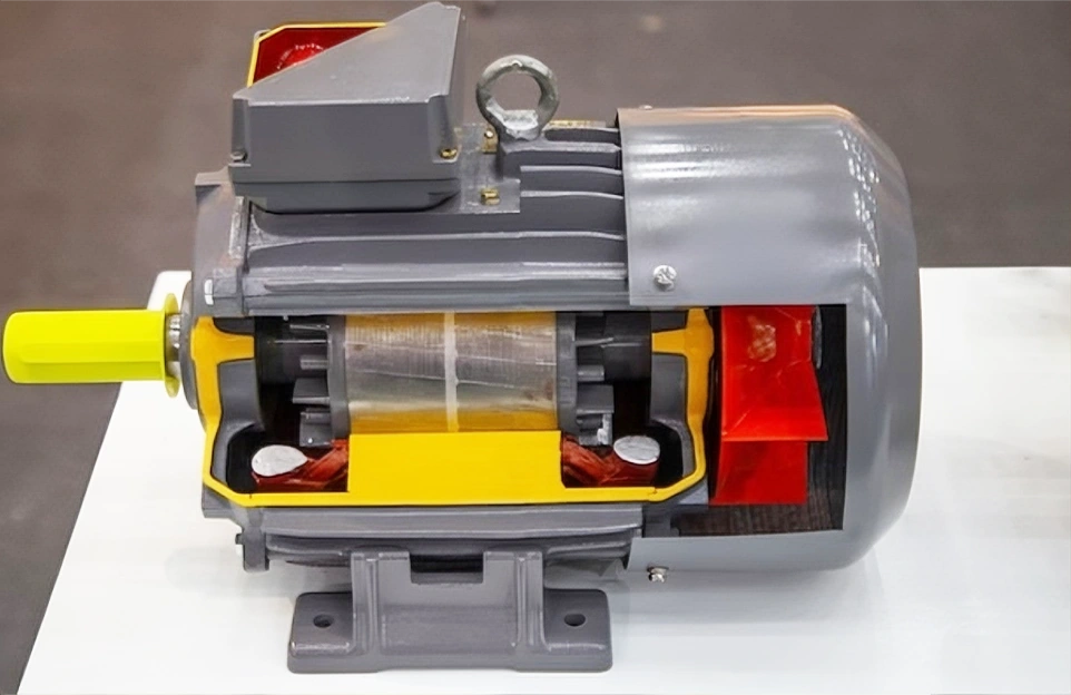
A single-phase motor has a stator and a rotor. The stator carries a running winding and a starting winding. With the capacitor, the starting winding creates a phase shift that gives the motor its rotation direction. The rotor turns inside this field and drives the cooling fan.
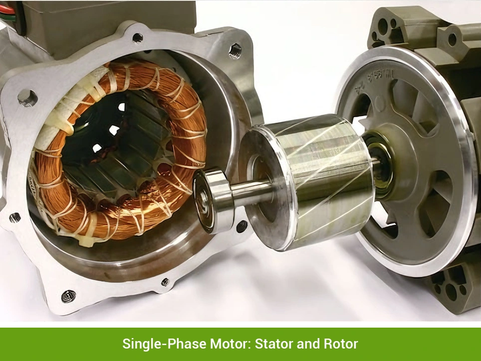
Single phase motors rely on the starting winding and capacitor to create a directional magnetic field. The control box links these components, and its wiring pattern sets the motor's start direction. Changing these connections will change the rotation direction.
Common causes of reverse rotation
- Incorrect or mixed wiring inside the control box
- Wiring not restored correctly after motor replacement or repair
- Mistaken belief that flipping the plug can change rotation
Correct adjustment method
The rotation of a single-phase motor is adjusted through the control box by changing the connection of the starting winding.

Step 1: Power off and open the control box
Cut the power completely, then open the rear control box or cover to access the terminals and bridging pieces.
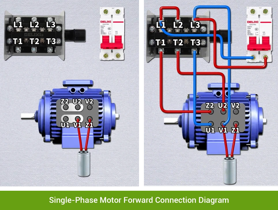
Step 2: Check the wiring diagram on the motor
Confirm the diagram on the motor to identify the correct connection layout before making any changes.
The diagram shows the standard wiring layout for normal forward rotation.
Terminal meanings
| Symbol | Meaning | Direction impact |
| U1 / U2 | Main winding terminals | No |
| Z1 / Z2 | Starting winding terminals | Yes |
| V1 / V2 | Auxiliary internal points | No direct impact |
| C (capacitor) | Creates phase shift | Indirect |
| L1 / L2 / L3 | Forward reverse switch input | No |
| T1 / T2 / T3 | Forward reverse switch output | Controls direction |
| Breaker | Power protection | No |
Terminal labels may vary by brand. Always follow the wiring diagram provided inside the motor terminal box.
Copper Bridging Plate
Changing the plate position, either horizontal or vertical, switches the connection between the running and starting windings. This simple structure allows easy direction adjustment.
Steps
- Loosen the terminal screws so the plate can slide out. Do not remove the screws completely.
- Move the plate to the forward rotation position: U1–V1 and Z2–U2.
- Tighten the screws and press the plate firmly to ensure good contact. Loose contact may prevent the motor from starting.
- Check for debris or exposed metal and close the terminal box.
This method applies only to motors with adjustable bridging plates. Always follow the wiring diagram in the terminal box, as layouts vary by manufacturer.
Wire Connections
Some motors use a forward reverse switch and external wiring to change direction. In this setup, the switch and wires perform the same role as a bridging plate by switching the starting and running windings.
Steps
- Disconnect the power completely to remove any risk of electricity.
- Check the wiring diagram and confirm the correct forward rotation connections, especially the starting winding (Z1, Z2) and running winding (U1, U2, V1).
- Locate the two wires that bridge the terminals and verify whether their current position matches the forward diagram.
- Move the bridging wires to the required terminals.
- Tighten all screws and close the housing to ensure reliable contact.
- Test the motor for 1–2 seconds. If it still reverses, recheck the bridging points against the diagram.
If you are not familiar with the circuit or switch structure, have a qualified technician adjust the wiring to avoid short circuits or motor damage.
Three phase motor rotation and adjustment
A three-phase motor also consists of a stator and a rotor. The stator contains three evenly spaced windings. When supplied with three phase power, these windings create a stable rotating magnetic field that drives the motor. The rotor sits inside the stator and turns with this field, powering the shaft and the cooling fan at the rear.
Unlike single phase motors, a three phase motor does not use a starting capacitor or an extra winding for direction. Its rotation is determined entirely by the phase sequence of the three phase power supply.
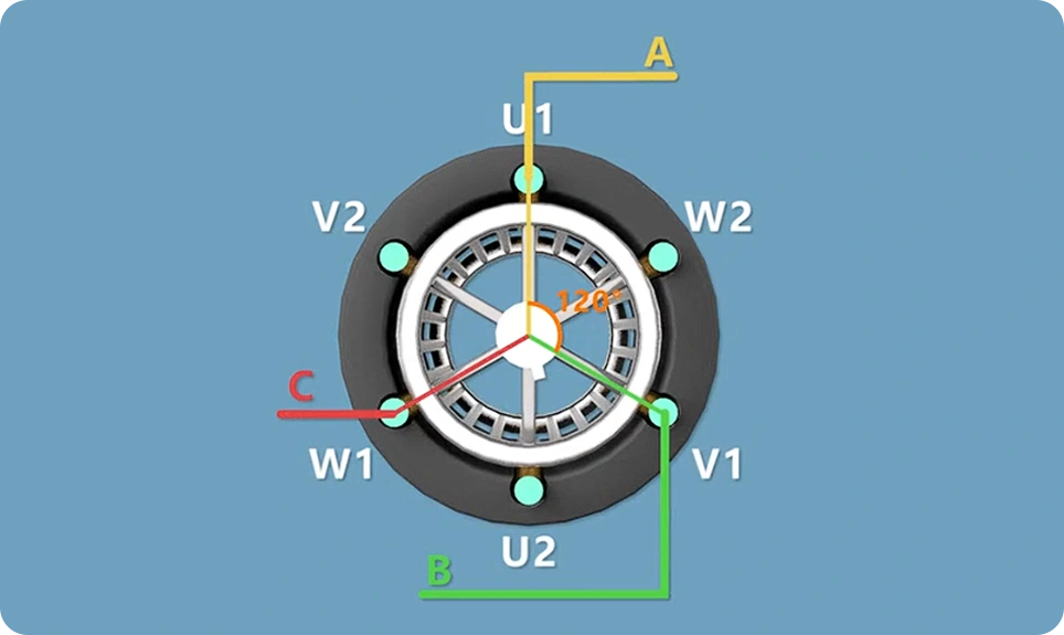
This diagram shows how the three phase stator windings are arranged. Each phase (U, V, W or A, B, C) is placed around the stator in a fixed sequence.
- U phase (A phase) winding
- V phase (B phase) winding
- W phase (C phase) winding
The three currents are 120 electrical degrees apart. As they act on the windings in sequence, they create a rotating magnetic field that drives the rotor.
When the phase order is U → V → W (or A → B → C), the field rotates in one direction.
If the order becomes U → W → V (or A → C → B), the field reverses.
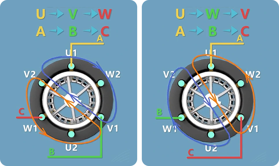
The stator structure stays fixed. Changing the order of the three phase wires reverses the magnetic field, so swapping any two phases will change the motor's rotation direction.
Common causes of reverse rotation
- L1, L2, L3 connected in the wrong order
- Phase sequence changed after repairs
- Motor or cable replacement altering phase order
- New or temporary power source with different sequence
- Generator output not matching site phase
- Incorrect reconnection after power loss
Correct adjustment method
Three phase windings follow a fixed layout, and the motor direction depends on the phase sequence. Changing the order of the incoming phases will reverse the magnetic field and the motor direction.
Steps
- Cut power completely.
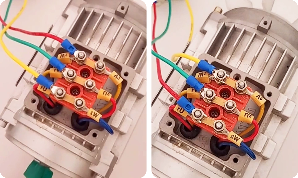
- Open the terminal box and locate U1, V1, W1.
- Take a photo of the original wiring.
- Swap any two-phase wires, for example U1 and W1.
- Tighten all terminals securely.
- Restore power and run a brief test.
- Check the die rotation to confirm the correction.
Keeping the die in the correct rotation direction is vital for consistent output and longer service life. After any installation or wiring change, run a quick test to confirm the direction. This prevents blockage, excess wear, and unnecessary downtime.
Need Some Help?
Contact us quickly and we will reply you within 24 hours. We will not disclose your information.